Placement and Routing Reference
An important aspect of building a circuit layout is the placement and routing of cells.
In IPKISS, this is done using i3.Circuit.
This placement and routing function works by choosing a set of instances, and defining specifications (placement, joining, alignment, how to connect, …) that describe how these instances should be placed and connected. The different specifications for placement and routing are listed below.
Functions and classes
The main class to use for building circuits is i3.Circuit. It is an easy-to-use class built around the core algorithm i3.place_and_route, which performs the placement and routing in the layout view.
i3.Circuit also uses i3.NetlistFromLayout, so that the netlist is automatically extracted from the layout. This enables layout-accurate circuit simulations.
Function to place and route a series of instances with the help of placement specifications and connectors. |
A PCell which derives its layout, netlist and model from a set of specifications in order to create a circuit. |
Specifications
The placement specifications are the following:
Join instances together. |
|
Specifies that an instance or its port should be placed on a given position and angle (angle is optional). |
|
Specifies that an instance (inst1) or a port (inst1:port) should be placed relative to another instance (inst2) or a port (inst2:port) with a given offset (x, y) and an angle (optional). |
|
Specifies that instances or ports should be aligned horizontally. |
|
Specifies that instances or ports should be aligned vertically. |
|
Specifies that a horizontally mirrored version of the component must be placed. |
|
Specifies that a vertically mirrored version of the instance must be placed. |
Note
Always be as specific as possible when providing the placement specifications. The placement engine will change the positions of instances that are specified in the specifications list.
For instance, if you have multiple specs without using Place, that tells the placement engine that the location of the full circuit (or at least that one instance) is not important. The instances will still be placed relative to each other as specified, but their position might change when you add more specs. By using Place, you anchor your circuit.
The routing specifications are the following:
Scalar connectors
Base class for connectors. |
|
A connector that uses |
|
A connector that uses |
|
Connector for creating an as simple as possible bend between two optical ports based on the given rounding parameters. |
Bundle connectors
Connects multiple ports together using a bundle of waveguides separated by a fixed distance. |
Fanouts for Bundle connectors
Create S-bend-like routes that fanout all the start ports to evenly spaced outputs. |
Route control
Control points
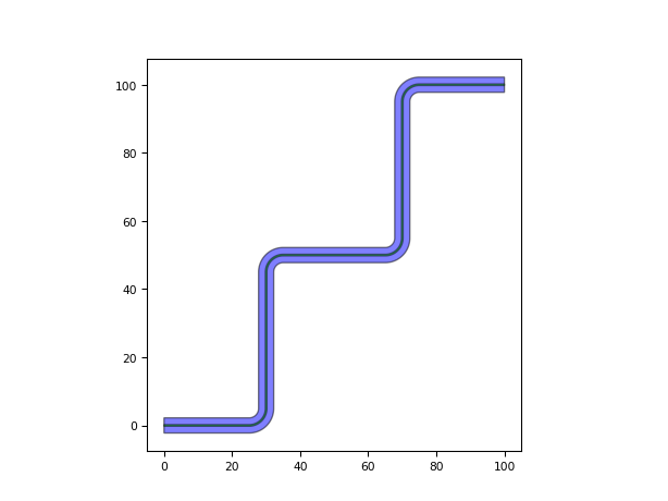
Control points allow you to specify certain points through which the route should go.
from technologies import silicon_photonics
import ipkiss3.all as i3

start_port = i3.OpticalPort(name='start', position=(0, 0))
end_port = i3.OpticalPort(name='end', position=(50, 50), angle=180)

wg = i3.ConnectManhattan.connect(start_port, end_port, control_points=[(10, 20), (30, 30)])
wg.get_default_view(i3.LayoutView).visualize()
Horizontal and Vertical control lines
i3.ConnectManhattan and i3.RouteManhattan allow the definition of horizontal and vertical control lines.
Horizontal control point class. |
|
Vertical control point class. |
i3.H and i3.V represent Horizontal and Vertical lines on a grid.
They accept a single parameter representing an X-value for i3.V and a Y-value for i3.H.
Note
When supplying i3.H and i3.V as control lines they have to be alternated as the lines should cross each other in the order you want the routing to go.
Below are some examples using i3.ConnectManhattan:
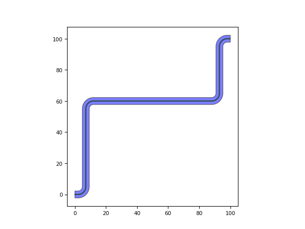
An example showing the syntax:
from ipkiss3. import all as i3

control_points = [i3.V(10), i3.H(40), i3.V(35)]

connector = i3.ConnectManhattan('inst1:out', 'inst2:out', control_points=control_points)
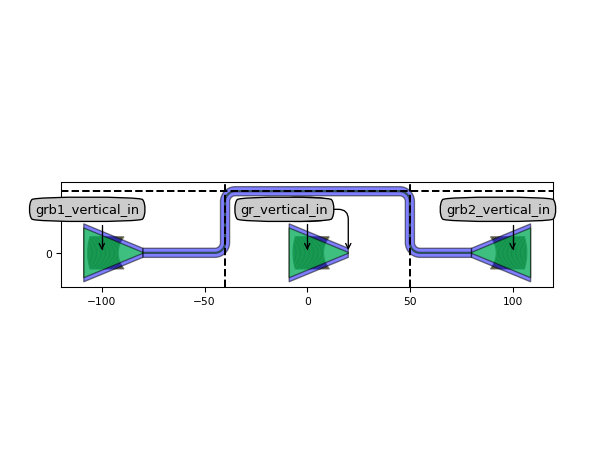
An example showing the usage in an obstacle avoidance situation:
from technologies import silicon_photonics
from picazzo3.fibcoup.curved import FiberCouplerCurvedGrating
import matplotlib.pyplot as plt

# Placing the components in a circuit
gr = FiberCouplerCurvedGrating()
control_points = [i3.V(-40), i3.H(30), i3.V(50)]
circuit = i3.Circuit(
    insts={
        'gr': gr,
        'grb1': gr,
        'grb2': gr
    },
    specs=[
        i3.Place('gr', position=(0, 0)),
        i3.Place('grb1', position=(-100, 0)),
        i3.Place('grb2', position=(+100, 0), angle=180),

        i3.ConnectManhattan(
            'grb1:out', 'grb2:out',
            control_points=control_points,
        )
    ]
)

lay = circuit.Layout()
lay.visualize(annotate=True, show=False)

plt.axvline(x=-40, color='k', linestyle='--')
plt.axhline(y=30, color='k', linestyle='--')
plt.axvline(x=50, color='k', linestyle='--')
plt.show()
Relative route control
Sometimes positions or values are only known relative to an anchor like the start or end port. In that case you can use symbols to represent these unknowns, and IPKISS will fill in the appropriate values.
Symbolic object that represents a start value or position. |
|
Symbolic object that represents an end value or position. |
|
Symbolic object that represents a previous value or position. |
from technologies import silicon_photonics
import ipkiss3.all as i3
from ipkiss3.all import START, END
# Define some ports
port1 = i3.OpticalPort(position=(0.0, 0.0), angle=0.0)
port2 = i3.OpticalPort(position=(100.0, 100.0), angle=180.0)
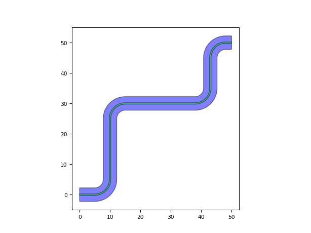
control_points = [START + (30, 10), # control point at (30, 10) relative to the start port
(50, 50), # control point at (50, 50) relative to (0, 0)
END - (30, 10)] # control point at (-30, -10) relative to the end port
wg = i3.ConnectManhattan.connect(port1, port2, name='manhattan_connection',
control_points=control_points,
bend_radius=5.0)
lo = wg.get_default_view(i3.LayoutView)
lo.visualize()
# Similarily it is possible to define relative i3.H and i3.V control points
wg = i3.ConnectManhattan.connect(port1, port2, name='manhattan_connection2',
control_points=[i3.H(END - 40)],
bend_radius=5.0)
lo = wg.get_default_view(i3.LayoutView)
lo.visualize()